
Home / Installing a Gate / Sliding Gate Installation Guides
Tips & advice
Sliding gate installation guide
Feel free to ask us about any install queries you may have, we’re happy to help.
Click here to download the Southern Gates Slide Install Guide.
Or simply scroll down to view the guide on this page.
Watch the video overview below:
Contents
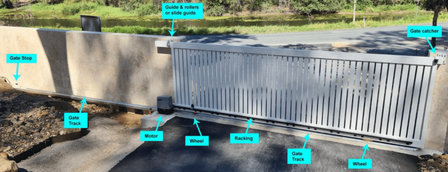
1. Typical Slide Gate Layout and Components
Overview:
End catch assembly:
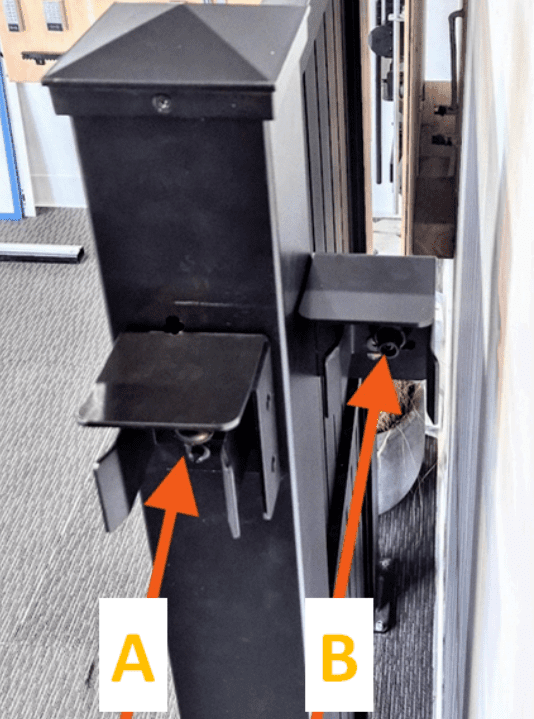
Two options for configuration:
A: Butt into end the post
B: Slide behind the post
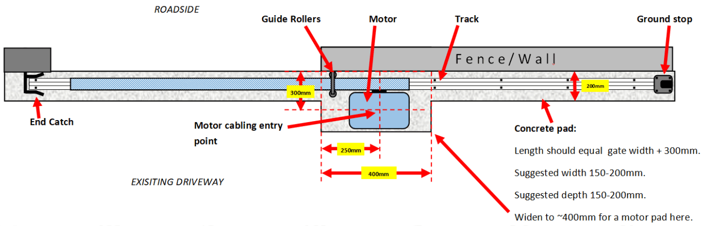
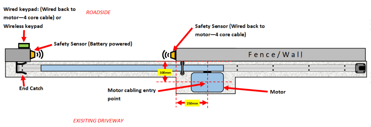
Top down layout and typical measurements
- The configuration of your gate may be the opposite (Mirror image) to the below layout
- It isn’t necessary to adhere to the below figures precisely and every property differs slightly, so consider these measurements a guideline only
2. Manual Slide Gate Installation
3. High level steps - if you are confident with the install, and just want a basic overview.
- Pre cable and lay concrete foundation
- Mark Track location
- Attach gate wheels
- Attach guide roller bracket
- Position gate – confirm track location – remove gate – anchor track down
- Reposition gate – adjust guide rollers and fasten securely
- Fit ground stopper and end catch assembly
- Test operation
4. Detailed steps - we suggest everyone follow these
Step 1 — Pre cabling
1. Install pre cabling and/or conduit and draw wire for electrics (Even if you’re not considering having your gate automated with a motor, it’s smart and relatively low-cost, to add this cabling now for future proofing.
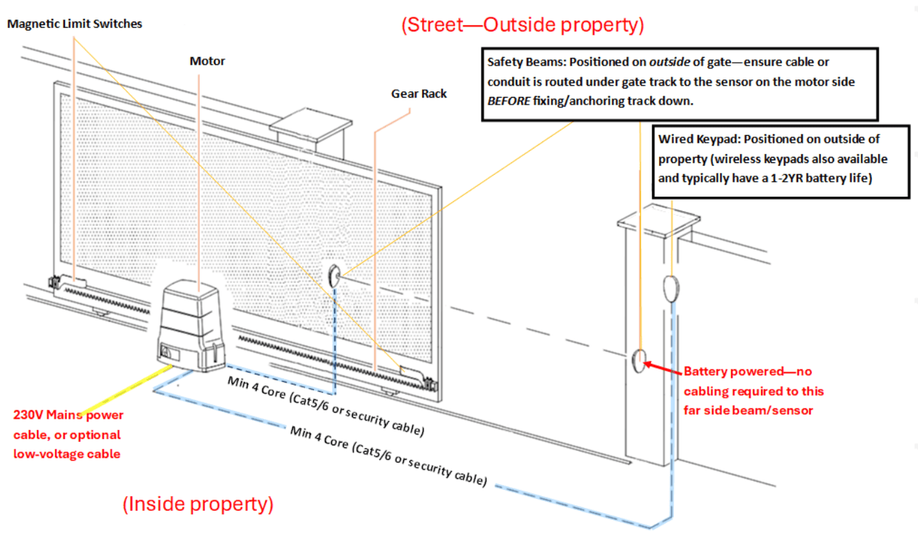
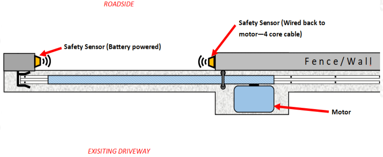
The below diagrams show the layout of components for a basic automated gate and wiring requirements, including where the cable needs to be positioned for the motor.
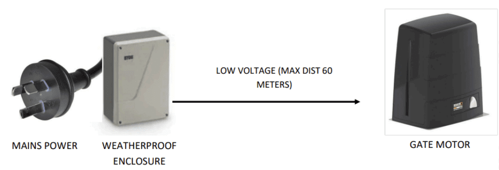
Motor power:
- Our motors can be either supplied with Mains power (230V AC)
OR
- We have optional low-voltage kits – Designed for easy installation—just plug it in and run low voltage cable to your gate motor – the low voltage cable does not need to be buried (Unlike mains power cable), so it can save considerable installation costs
Safety beams:
- These are sensors that sit either side of the driveway and prevent the gate closing route cable underneath where the track will if there is an obstruction – car / human / pet etc
- 4 Core cable needs to be run from the motor to one safety beam —remember to be placed. The 2nd safety beam operates with a battery.
Keypads: (Optional)
- Wireless keypads are an option saving you the need to run cable for these if is going to be difficult/costly
- A 4 core minimum is required though we suggest an 8 core cable – run back to the gate motor
Step 2 - Concrete footing
1. Mark the gate opening and sliding direction with pegs or spray paint.
2. Ensure the sliding area is clear of obstructions for at least 1.5 × the gate opening width.
3. If needed, pour a concrete strip footing for the track
(We do not recommend attaching the track directly to asphalt driveways. Asphalt is too malleable and does not provide adequate anchoring support for the track.)
- Minimum 200 mm wide × 150 mm deep
- Long enough for the full travel of the gate – plus an additional 300mm, beyond the end of the gate on the opening side, with the gate fully open – this is to mount a ground stopper.
- Widen to 450mm where the motor will sit (If allowing for this) – see top down layout and dimensions on previous pages for guidance
- Run a string line to keep the footing straight and level.
- Include a length of rebar for reinforcement
Ideally allow 7 days curing time before attaching hardware or installing the gate.
Step 3 — Position the track
1. Lay the track sections along your marked center line (under the string line), but do not anchor this down yet.
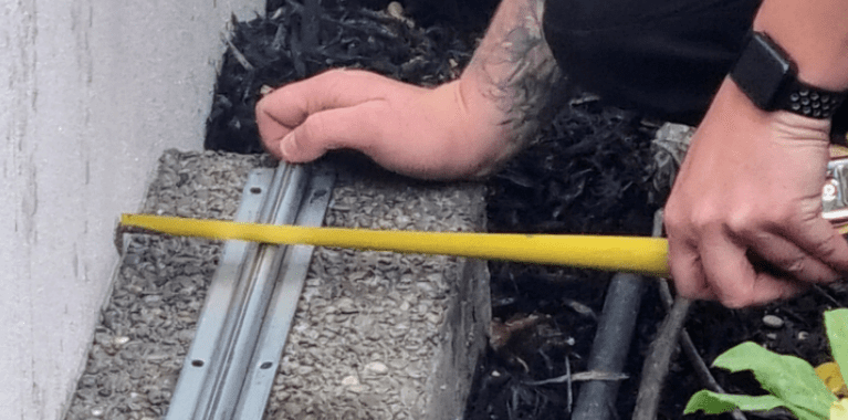
2. If you are confident of your track’s final position, you can anchor it down using the supplied expansion anchors – drill 6.5mm x 50mm holes into the concrete, insert each anchor and hammer the pin home. (Ensure the track remains straight and level as you fix it, and that separate track sections are butted up to each other.)
or
If you are not confident of your tracks final position, leave it sitting in place but not anchored down, and move to the next step
Step 4 — Fit the wheels to the gate
1. Lay the gate gently on its side on timber packing so paint/finish is protected and the base is accessible.
2. Locate the wheel mounting cutouts on the base of the gate – and depending on the wheel type you are using;
- Recessed wheels: you will see cutouts on the base where the wheel sits into the gate profile. Install the wheel so most of the wheel recesses into the hole.
- External-bracket wheels: mount the wheel/bracket adjacent to the cut outs.
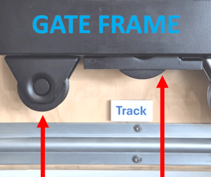
3. Use the tek screws supplied, fasten the wheels taking care to ensure they are aligned with the gate frame
⚠️Careful — do not overtighten tek screws. Release your driver/drill trigger as soon as the screw thread “bites” the metal, then finish tightening slowly. Over torquing/tightening can strip the metal or distort the wheel mount.
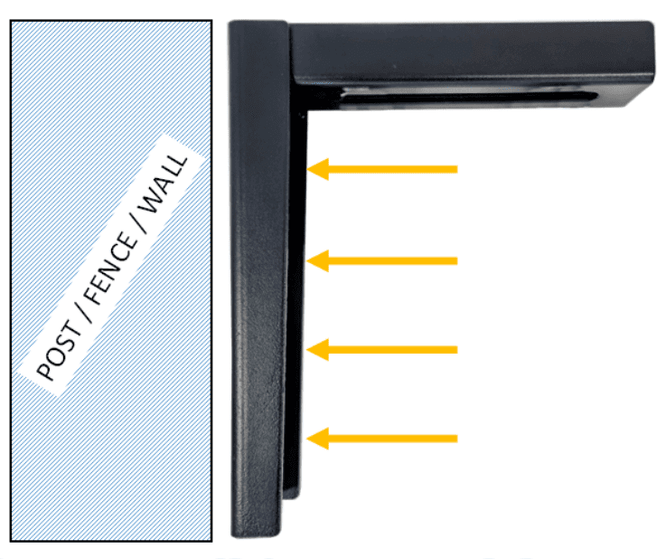
Step 5 - Guide Roller bracket
1. Attach your guide roller bracket
a. Use min 50mm coach bolts if attaching to timber, or min 12g x 20mm Tek screws if attaching to metal. (Note SGL do not supply these fasteners)
b. Ensure the height of the bracket allows the gate to pass underneath the bracket
i. Taking into account the finished height of the gate once sitting on wheels and track.
ii. Taking into account this height may change as the gate rolls fully closed to fully open (Unflat ground), so ensure the bracket clears the bracket at its highest point.
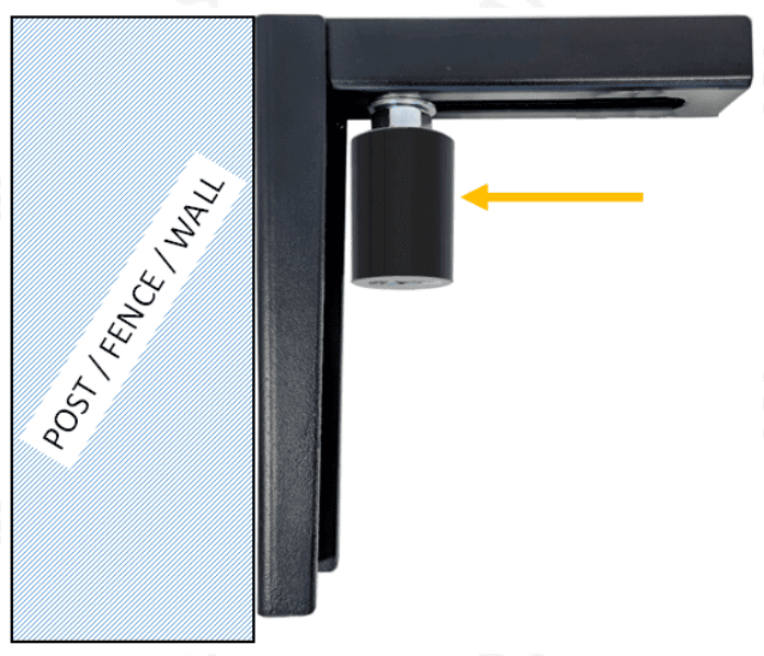
2. Fit the inside guide roller only, and tighten.
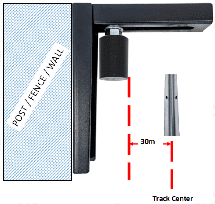
3. Take the inside point of this guide roller, and transfer its position down to the concrete – from this point, measure 30mm inwards (towards property) and mark this point as the center line for your track and run a string line or laser to identify this point at the closing and full open points of the gate. Do not fix track yet though – following the next steps first.
Step 6 — Check gate & track position, & anchor track down
(If you anchored your track in step 3, you can skip this step)
1. Carefully lift the gate onto the track so it sits on the wheels. With the gate sitting on the track, check its position relative to your fence line and closing point. Roll the gate from full open to closed positions. If the gate’s position needs adjusting, carefully shunt the gate and track together until it sits correctly in relation to the fence/post.
(⚠️WARNING – be careful not to let go of the gate as at this point it is not being held up by any guide rollers)
2. When you’re confident of the gate position, mark the track location onto the concrete/footing (scribe or mark anchor hole positions).
3. Carefully remove the gate from the track and set it aside
4. Now anchor the track down permanently using the supplied expansion anchors – drill 6.5mm x 50mm holes into the concrete, insert each anchor and hammer the pin home. (Ensure the track remains straight and level as you fix it, and that separate track sections are butted up to each other.)
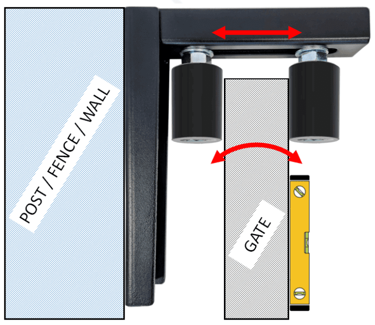
Step 7 — Position the gate and adjust guide rollers
1. Carefully lift and set the gate back onto the anchored track.
2. Fit the inside roller and finger tighten this making sure there is at least a 2mm gap between the roller and the gate, to prevent it binding up.
- Put a spirit level on the side of the gate, to check it’s vertical – adjust guide rollers if necessary
3. Slowly roll the gate fully open and fully closed while watching for:
(⚠️WARNING – be careful not to slide the gate along so it rolls out of its rollers and falls over)
- Misalignment or dragging on one side
- Lateral wobble or jumping the track
- Any rubbing on posts/fence
Step 8 — Fit ground stopper
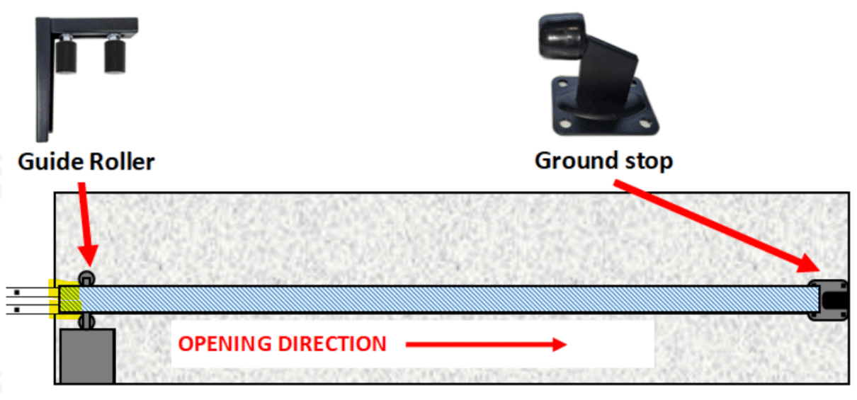
2. Fix the ground stopper in place – use masonry anchors
Step 9 — Fit end catch assembly
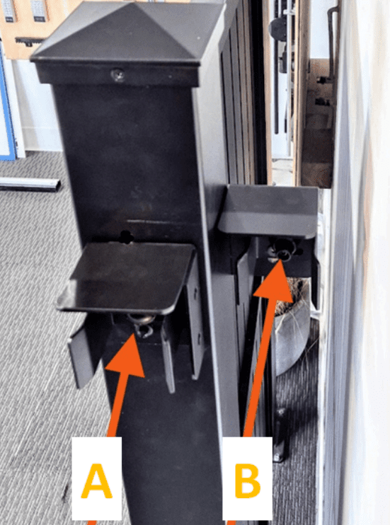
There are two main configurations for the end catch
A: Butt into end the post
B: Slide behind the post
1. Carefully slide the gate into its closed position to determine how it meets your fence/wall/end post, then mount the anti theft bracket so that the top of the gate slides just under the top piece – as pictured.
⚠️We supply both LEFT hand and RIGH hand anti theft brackets

2. Fix the gate nose to the end of the gate using supplied tek screws – careful not to overtighten the screws

3. Carefully slide the gate into the end catch to ensure it lines up – adjust if necessary
Step 10 — Install lock/latch if required
Depending on your situation;
Manual sliding gates (No electrics)
If you’re not installing electrics to automate your gate, you’ll want to fit a lock/latch to secure the gate closed when shut – there are a few options available and it’s best to discuss these with us so we can help determine the best one to use.
Automatic sliding gates (Motorised)
If you are fitting electrics to automate your gate – the motor will lock the gate securely in place when closed, and there’s no need to fit a separate lock/latch.
Manual now, but may motorise in the future
You’ll likely want some sort of lock/latch, but keep in mind that if you do decide to add electrics in the future – any manual lock/latch fitted would then become redundant and need to be removed, leaving marks/holes where they were fitted.
Step 11 — Complete Final checks
- Check both ground stop on the opening side, and end catch assembly are secure and stop the gate safely preventing it from sliding outside the guide rollers
- Check that the gate rolls smoothly by hand for full travel from closed to open to closed.
- Check that there is no binding, no significant side-to-side play, and wheels track correctly.
- Check that the guide rollers support the gate and 2–3 mm clearance is maintained between roller and gate
5. Gate Automation and Electrics
Before you jump into fitting automation - please read.
All of our gate motors are supplied with the manufacturer’s factory installation manual. These manuals provide detailed, brand-specific instructions for proper installation and setup. As each motor is unique, we suggest you refer to these guides, but we provide some generic information below that is universal to almost all installs.
We are happy to offer after-sales technical support via phone and email to assist you during your installation.
Additionally, we work with a large network of experienced and reputable installers and can recommend a professional in your area. They can provide:
- Complete, start-to-finish installation – A fully hands-off service covering the entire gate and automation setup.
- Automation installation only – If you are confident installing the gate and ensuring it operates smoothly manually, one of our trusted installers can complete just the electrical automation portion. This option can help reduce overall installation costs.
Gear Racking
Gear rack is fitted along the length of a sliding gate so that the gate motor can drive the gate open and closed. The motor contains a drive gear (pinion) that engages with the teeth of the gear rack. As the motor turns the pinion, it pushes or pulls the rack, causing the gate to slide along the track.

1. Start With the First Rack Section
Our gear rack is supplied in 1 metre lengths. Take the first length and place it on the gate with the gate in the fully closed position.
⚠️ Ensure the rack teeth engage with the motor pinion but leave a 1-2mm clearance – you may have to raise the motor mounting, to accommodate the racking.
2. Release the gate motor
Manually release the gate motor so the pinion spins freely – follow manufacturers manual for this.
3. Install Remaining Sections
Slide the gate along the track as required and continue fitting the remaining rack sections along the gate – each section dove tails together. ⚠️ Ensure the rack teeth engage with the motor pinion but leave a 1-2mm clearance.
4. Check Movement
Manually slide the gate fully open and closed to confirm smooth engagement with the motor gear.
5. Tighten Fixings
Once alignment is confirmed, fully tighten all Tek screws.
6. Cut excess rack
You’ll likely have excess racking sticking beyond the end of the gate after fitting the last piece of racking – simply cut this excess off with an angle grinder
Limit Switches
Magnetic limit switches tell the gate motor when the gate has reached its fully open or fully closed position. Magnets mounted on the gate pass a sensor on the motor, allowing the control board to stop the motor at the correct points. This ensures accurate stopping and prevents the gate from over-traveling.

⚠️Important: Two magnetic limit switches are supplied — one for the fully closed position and one for the fully open position. Ensure each magnet is installed at the correct end of the gate travel so the motor stops in the intended positions.
⚠️Important: Some gate motors have a factory default travel direction. If the gate moves in the opposite direction to the intended opening direction, the motor direction setting may need to be reversed in the motor controller before setting the limits.
⚠️Important: Position and fit the limit switches so that the gate motor stops the gate before hitting any physical limit (End catch on closing side, ground stop on opening side)
Follow manufacturers manual for instructions on how to correctly fit and set up the limit switches – each brand differs slightly.
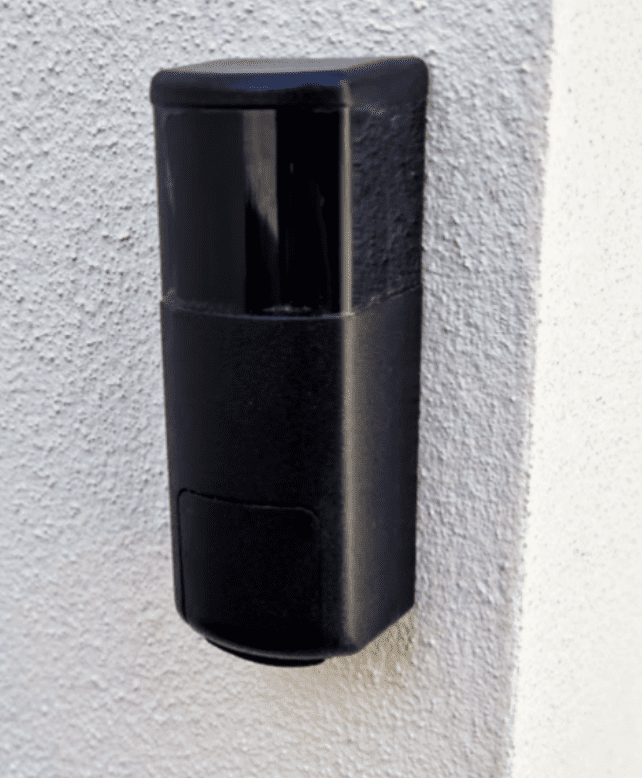
Safety Beams (AKA Photocells or Safety Sensors)
Infrared safety beams provide a safety barrier across the gate opening. A transmitter sends an infrared beam to a receiver on the opposite side. If the beam is interrupted by a vehicle, person, or object while the gate is closing, the motor will stop and reverse the gate to prevent injury or damage.
Basic Infrared Safety Beam Installation
1. Mount the Beams
Install the transmitter and receiver on opposite sides of the gate opening, facing each other so the beam crosses the driveway. Position the beams approximately 500–600 mm above ground level, or as recommended by the manufacturer.
2. Connect the Cabling
Connect the existing beam cable to the transmitter (Tx) unit as required by the motor controller – see the manufacturers manual for correct wiring connections. The receiver (Rx) unit operates using an internal battery, so no wiring is required on that side.
3. Align the Beams
Adjust the units so the transmitter and receiver are directly aligned. Most units have an indicator LED or buzzer that lights/sounds if units aren’t aligned or are obstructed.
4. Check settings in the motor and test operation
Check the manufacturer’s motor manual, regarding activating the safety beam feature and adjusting settings. Close the gate and break the beam during closing – the gate should stop immediately.
5. Secure the Units
Once alignment and operation are confirmed, fully tighten all fixings and weatherproof cable entries if required.
Remotes
Key fob remotes must be paired with the gate motor receiver before they will operate the gate.
Because programming procedures vary between motor models, refer to the manufacturer’s installation or programming manual for instructions on how to add or remove remotes from the system.

Other accessories
For guides on any of the below accessories, please refer to the manufacturers user manuals supplied with the hardware – each brand has specific instructions unique to their product. If you’re missing a user manual, let us know and we can provide one for you.
- Keypads wired or wireless
- Exit sensors
- Exit buttons
- Intercomms
- Ground Loops
Still not sure where to start?
We are here to help
Get in touch with us and let our team help you choose the right gate to suit your needs
STILL NOT SURE WHERE TO START?
We are here to help
Get in touch with us and let our team help you choose the right gate to suit your needs,
Sliding gate
What are the benefits
Use less space
Homeowners often opt for sliding gates for space efficiency. Sliding gates require minimal space when opening and closing, providing more room for gardens or yards. This makes them ideal for properties with uneven terrain, such as hilly areas.
More secure
Homeowners often opt for sliding or swing gates for space efficiency.
Better option in windy locations
If your property is subject to strong winds, a sliding gate is the preferred option as swing gates can suffer damage from strong winds.